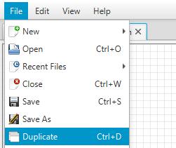
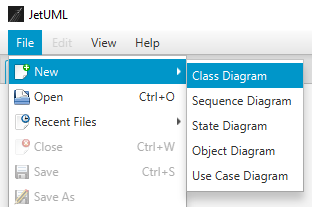
You can create a new diagram at any point using the menu command File | New. The diagram will open in a new tab.
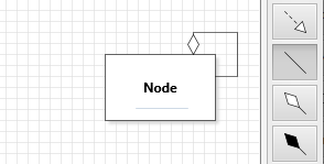
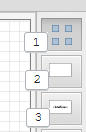
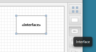
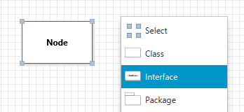
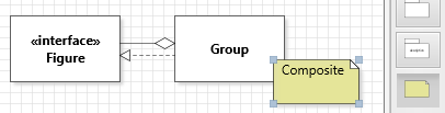
Selecting a node type in the toolbar enables the corresponding Node Creation tool. With a Node Creation tool enabled, click on an empty space in the diagram to create a new node of that type. Rolling over the tool in the toolbar shows a tooltip with the name of the node type.
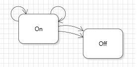
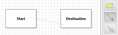
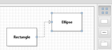
To create an edge between two nodes, select an Edge Creation tool in the toolbar, click in the start edge, then start dragging with the mouse. This will enable a rubber band view of the start and end nodes for the edge. Release the mouse on the destination edge to complete the operation. Edges are laid out automatically: to control their path it is necessary to move their start and end nodes. The edge creation operation will not have any effect if the edge type is not a valid way to connect the selected nodes.
To select diagram elements individually, enable the Selection tool and click on the element to select or deselect. To add or remove individual elements to/from the selection, hold down the Ctrl key while clicking on the element.
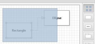
To select all elements in a region of the diagram, enable the Selection Tool, then click and drag from an empty space in the diagram. This will enable the Lasso tool.
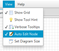
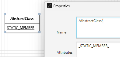
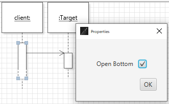
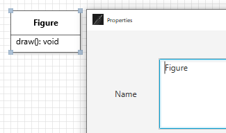
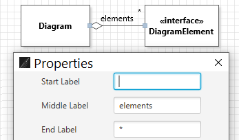
You can edit an element's properties by double-clicking it or by using the shortcut Ctrl-Enter on a selected element.
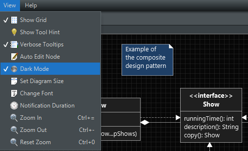
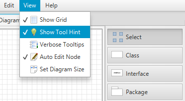
It is possible to view the name of each tool in the toolbar in full next to its icon. To toggle this feature, use the menu command View | Show Tool Hint.
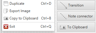
The toolbar is also available as a popup menu. Right-click anywhere to show it.
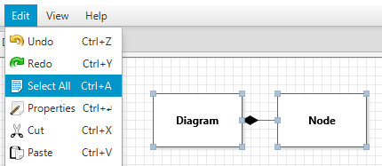
Use the menu command Edit | Select All (Ctrl-A) to select all elements in a diagram, for example to move the entire diagram as one.
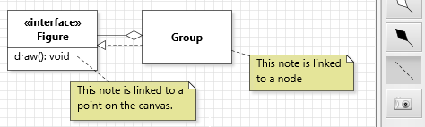
Use Note elements to annotate the diagram with complementary information.
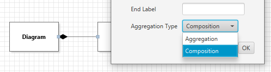
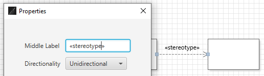
Certain types of edges can have associated labels. Edit the edge properties by double-clicking the edge or using the Ctrl-Enter shortcut.
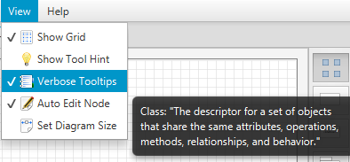
Use the menu command View | Verbose Tooltips to toggle verbose tooltips in the toolbar. Verbose tooltips provide an extended description of the meaning of UML elements available in the toolbar.
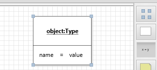
To add a field to an object, select the Field Creation tool from the toolbar and click within the desired object node. Accessing the fields' properties (Ctrl-Enter) allows to change the field's name and value.
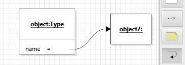
To add a reference to an object, select the Reference Creation tool from the toolbar, then drag a rubber band from the Value part of a field to the destination object node.
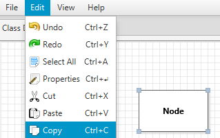
Use the Copy to Clipboard feature to copy a snapshot of the entire diagram to the system clipboard. The diagram can then be pasted easily into other applications. The feature is accessed using the File menu, the toolbar, or using the shortcut Ctrl-B.
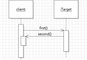
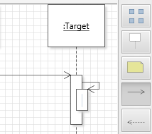
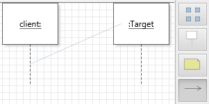
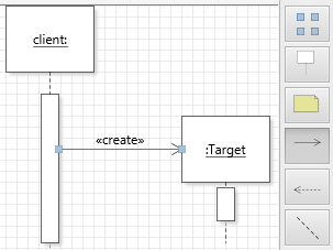
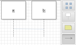
To create the initial call edge in a sequence diagram, select the Call Edge Creation tool and drag the rubber band from the life-line of the caller to the life-line of the callee.
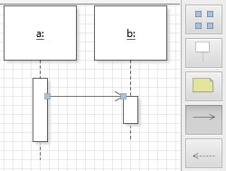
This will create the activation box for both the caller and the callee. To create additional call edges, drag from an activation box to a life-line.
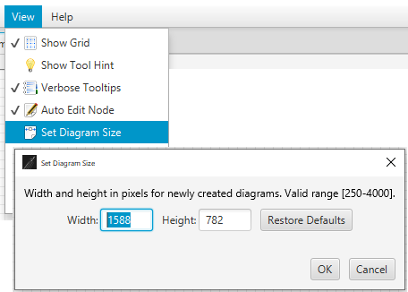
In JetUML diagrams have a fixed size. To change this size, use the menu command View | Set Diagram Size. The size will be used when creating new diagrams or opening diagram files. When opening a diagram, the size is automatically increased to fit the diagram if necessary. Larger diagrams decrease the tool's performance. The default values are in relation to the display size.
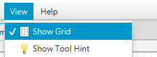
It is possible to control whether the grid is visible or not in a diagram. Use the menu command View | Show Grid to toggle this option. Diagram elements automatically snap to the grid whether it is visible or not.
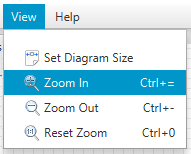
It is possible to zoom the diagram in and out up to a maximum of two levels in both directions. The commands are available through the View menu and through the shortcuts Ctrl-= (Zoom In), Ctrl-- (Zoom Out), and Ctrl-0 (Reset Zoom).
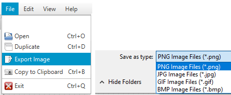
Use the menu command File | Export Image to save the current diagram as an image file. The image type is determined by the file extension selected from the Save as Type field.
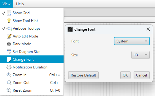
Use the menu command View | Change Font to change the font and size of the font used in the diagram. This setting only affects how the diagram looks.
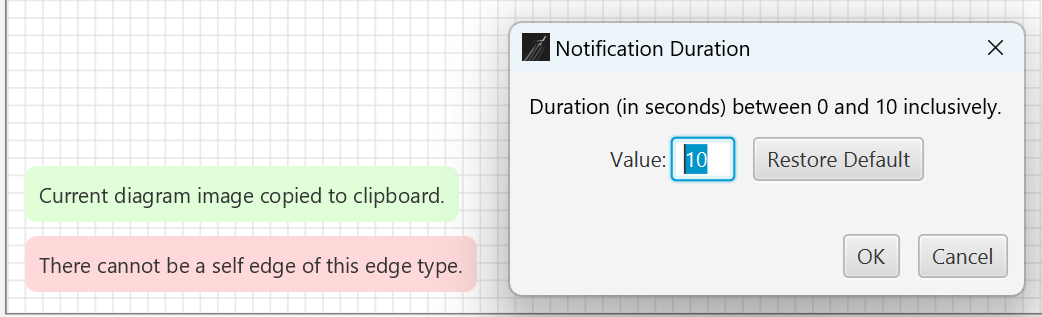
Errors and confirmations get reported as temporary notifications in the bottom left of the application window. It is possible to adjust the duration of the notifications. A duration of zero disables all notifications.
You can turn dark mode on or off by navigating to the menu command View | Dark Mode.